Micrel, Inc.
MIC2310
July 2008
18
M9999-070108-A
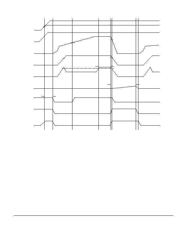
VCC = 12V, nominal
VGSPGH
V
GSPGH
V
PGH
VPGL
t
POC
IPOC
VREG = 5V, nominal
t
RETRY
tPOR
CC & VREG
ENABLE
GATE
V
OUT
I
LOAD
CRETRY
PWRGD
I_FLT
DISCH
VVREG(UVLOH)
Figure 6. Primary Overcurrent Fault with Auto-Retry to Reset the Circuit Breaker
HW_FLT Digital Output Asserted by a MOSFET DG
Short with ENABLE = LOW
In order to protect the system from the result of the
installation of a damaged MOSFET on the PCB, the
controller incorporates a MOSFET shorted DG
detection scheme whose operation is described in
Figure 7. With the applied V
CC
supply high such that
the internal V
REG
voltage is above the controllers
V
VREG(UVLOH)
threshold voltage, an elapsed POR timer,
and with the ENABLE input LOW, a weak current sink
at the GATE pin attempts to hold the GATE voltage at
0V. If there is a DG short on the MOSFET, the weak
current sink is not capable of holding the voltage at 0V
as the GATE voltage tracks the MOSFETs DRAIN
voltage. The voltage monitor circuit at the controllers
GATE pin will be triggered once the GATE voltage
crosses the V
GATEFT(EXT)
threshold voltage. The
HW_FLT digital output is subsequently asserted within
a delay approximately equal to the delay in the logic
circuits no additional timing circuit is required. To
clear the latched GATE voltage monitor circuit and to
reset the HW_FLT digital output, the applied V
CC
supply voltage must fall such that V
REG
is below the
controllers V
VREG(UVLOL)
threshold voltage.
发布紧急采购,3分钟左右您将得到回复。
相关PDF资料
MIC2341-2YTQ
IC HOT PLUG CTLR DUAL PCI 48TQFP
MIC2569YQS TR
IC POWER SWITCH CABLECARD 16QSOP
MIC2583R-MBQS TR
IC CTRLR HOT SWAP 200MV 16-QSOP
MIC2585-2MBTS TR
IC CTRLR HOT SWAP DUAL 24-TSSOP
MIC2586R-2BM TR
IC CTRLR/SEQ HOT SWAP 14-SOIC
MIC2587R-2BM TR
IC CTRLR HOT SWAP POS HV 8-SOIC
MIC2590B-5BTQ TR
IC PCI HOT PLUG CTLR DUAL 48TQFP
MIC2591B-2BTQ TR
IC PCI HOT PLUG CTLR DUAL 48TQFP
相关代理商/技术参数
MIC23150-4YMT EV
功能描述:电源管理IC开发工具 2.0A 4MHz HyperLight Load Buck Regulator - Evaluation Board
RoHS:否 制造商:Maxim Integrated 产品:Evaluation Kits 类型:Battery Management 工具用于评估:MAX17710GB 输入电压: 输出电压:1.8 V
MIC23150-4YMT TR
功能描述:直流/直流开关调节器 2.0A 4MHz HyperLight Load Buck Regulator
RoHS:否 制造商:International Rectifier 最大输入电压:21 V 开关频率:1.5 MHz 输出电压:0.5 V to 0.86 V 输出电流:4 A 输出端数量: 最大工作温度: 安装风格:SMD/SMT 封装 / 箱体:PQFN 4 x 5
MIC23150-4YMT-TR
功能描述:Buck Switching Regulator IC Positive Fixed 1.2V 1 Output 2A 8-VFDFN Exposed Pad, 8-MLF? 制造商:microchip technology 系列:HyperLight Load? 包装:剪切带(CT) 零件状态:有效 功能:降压 输出配置:正 拓扑:降压 输出类型:固定 输出数:1 电压 - 输入(最小值):2.7V 电压 - 输入(最大值):5.5V 电压 - 输出(最小值/固定):1.2V 电压 - 输出(最大值):- 电流 - 输出:2A 频率 - 开关:4MHz 同步整流器:是 工作温度:-40°C ~ 125°C (TJ) 安装类型:表面贴装 封装/外壳:8-VFDFN 裸露焊盘,8-MLF? 供应商器件封装:8-MLF?(2x2) 标准包装:1
MIC23150-55YMT TR
功能描述:直流/直流开关调节器 2.0A 4MHz HyperLight Load Buck Regulator
RoHS:否 制造商:International Rectifier 最大输入电压:21 V 开关频率:1.5 MHz 输出电压:0.5 V to 0.86 V 输出电流:4 A 输出端数量: 最大工作温度: 安装风格:SMD/SMT 封装 / 箱体:PQFN 4 x 5
MIC23150-55YMT-TR
功能描述:Buck Switching Regulator IC Positive Fixed 1.35V 1 Output 2A 8-UFDFN 制造商:microchip technology 系列:HyperLight Load? 包装:剪切带(CT) 零件状态:停产 功能:降压 输出配置:正 拓扑:降压 输出类型:固定 输出数:1 电压 - 输入(最小值):2.7V 电压 - 输入(最大值):5.5V 电压 - 输出(最小值/固定):1.35V 电压 - 输出(最大值):- 电流 - 输出:2A 频率 - 开关:4MHz 同步整流器:是 工作温度:-40°C ~ 125°C (TJ) 安装类型:表面贴装 封装/外壳:8-UFDFN 供应商器件封装:8-TDFN(2x2) 标准包装:1
MIC23150-CYMT EV
功能描述:电源管理IC开发工具 2.0A 4MHz HyperLight Load Buck Regulator - Evaluation Board
RoHS:否 制造商:Maxim Integrated 产品:Evaluation Kits 类型:Battery Management 工具用于评估:MAX17710GB 输入电压: 输出电压:1.8 V
MIC23150-CYMT TR
功能描述:直流/直流开关调节器 1.5A 4MHz HyperLight Load Buck Regulator
RoHS:否 制造商:International Rectifier 最大输入电压:21 V 开关频率:1.5 MHz 输出电压:0.5 V to 0.86 V 输出电流:4 A 输出端数量: 最大工作温度: 安装风格:SMD/SMT 封装 / 箱体:PQFN 4 x 5
MIC23150-CYMT-TR
功能描述:Buck Switching Regulator IC Positive Fixed 1V 1 Output 2A 8-VFDFN Exposed Pad, 8-MLF? 制造商:microchip technology 系列:HyperLight Load? 包装:剪切带(CT) 零件状态:停产 功能:降压 输出配置:正 拓扑:降压 输出类型:固定 输出数:1 电压 - 输入(最小值):2.7V 电压 - 输入(最大值):5.5V 电压 - 输出(最小值/固定):1V 电压 - 输出(最大值):- 电流 - 输出:2A 频率 - 开关:4MHz 同步整流器:是 工作温度:-40°C ~ 125°C (TJ) 安装类型:表面贴装 封装/外壳:8-VFDFN 裸露焊盘,8-MLF? 供应商器件封装:8-MLF?(2x2) 标准包装:1
